
Mechanical Engineer EIT Portfolio
Project Showcase
Explore a curated gallery of academic and personal engineering projects, demonstrating technical expertise and innovation.
Professional
Multibeam Sonar Deployment System
Marine Engineering | Structural Design | FEA
Mooring System for Antarctic Deployment
Mechanical Design | Analysis | Prototyping
Protective Winch Cover
Marine Equipment Design | Fabrication | Durability Optimization

High-Pressure Instrument Housing
Pressure Vessel Design | Marine Systems | Precision Manufacturing
Calibration Test Branch
Thermal Systems | Pressure Vessels | Instrumentation
Academic
VTOL SAR Drone Development
UAV Design | Systems Integration | Propulsion & Power Analysis
Automated Sorting System
Mechatronics | Embedded Systems | Real-Time Control
Mine Detection Robot (MARV-1N)
Mechanical Design | Robotics | Prototyping
Thermal Optimization of Mini Fridge
Thermal Systems | CFD | Design Optimization
Planetary Gearbox for Ferris Wheel
Mechanical Design | Analysis | Prototyping
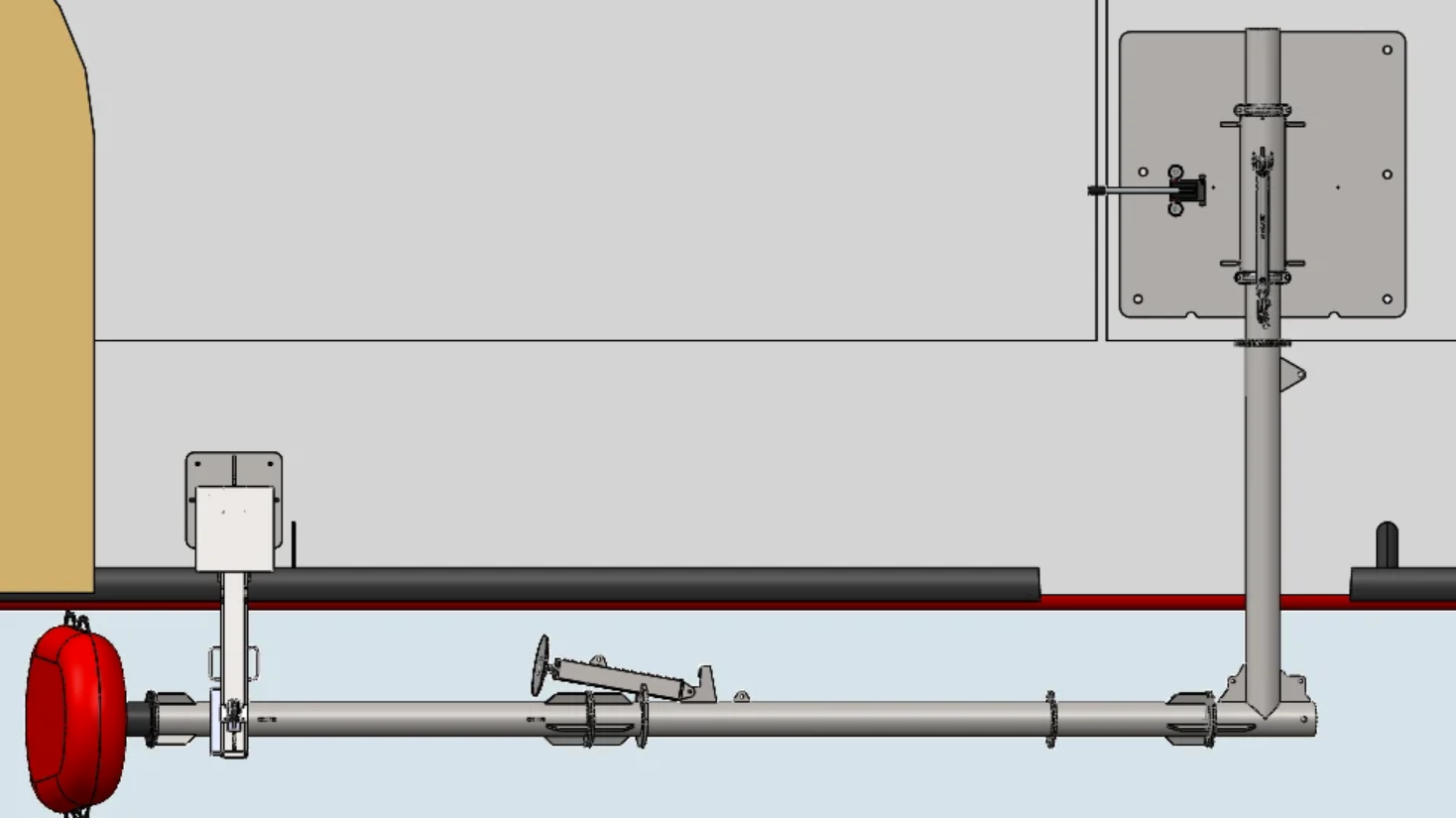
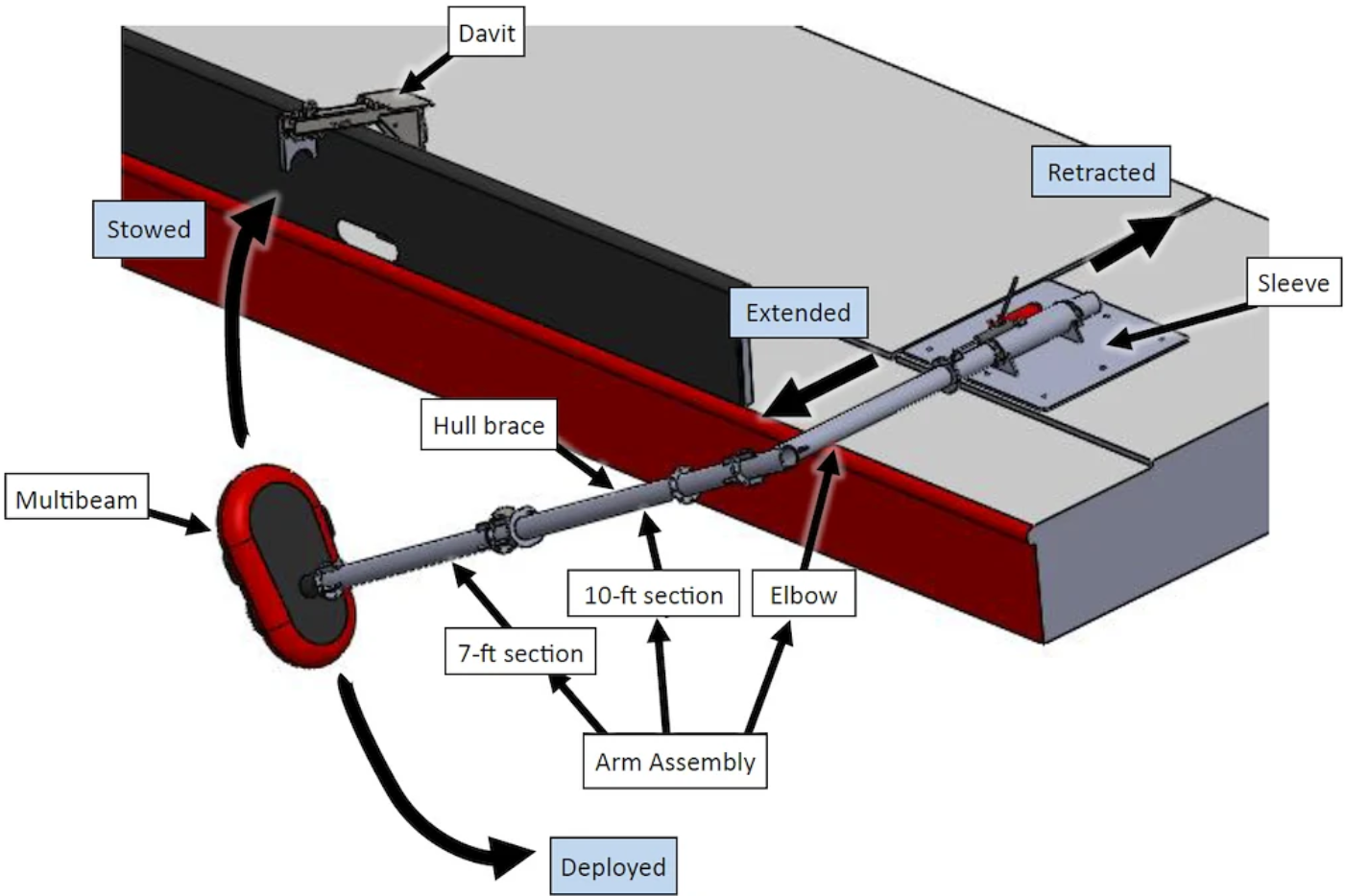
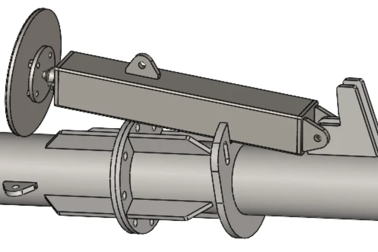
Multibeam Sonar Deployment System
Marine Engineering | Structural Design | FEA
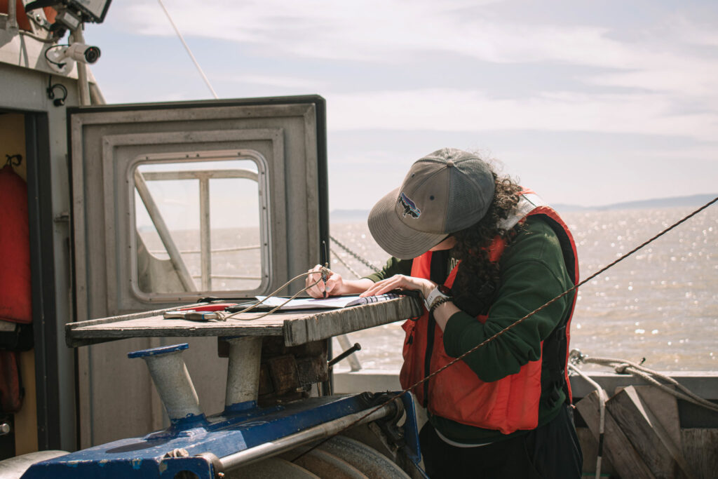
During a co-op with Ocean Networks Canada, a rugged deployment structure was required to support a multibeam sonar system used for seabed mapping from a large research vessel. The structure needed to operate reliably in cold, high-load marine environments while protecting sensitive sonar equipment during deployment and recovery.
Objective
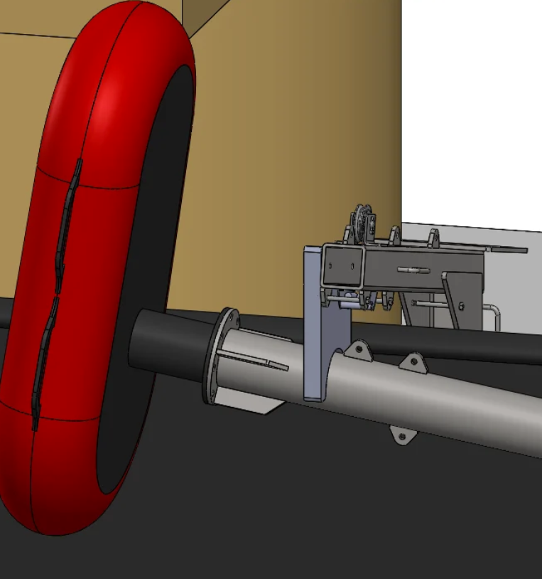
Design a corrosion-resistant structural frame capable of safely housing and deploying multibeam sonar equipment in harsh ocean conditions, with consideration for hydrodynamic loads, vortex shedding, and fabrication constraints.
Tools & Technologies
- SolidWorks · FEA stress simulation
- Marine-grade metals and coatings
- CNC machining · Welded structural assemblies
- Hydrodynamic load considerations
My Role & Contributions
- Led the structural design and material selection for the sonar deployment frame
- Performed FEA stress analysis under wave and impact loading conditions
- Identified and corrected vortex shedding risks through geometric design changes
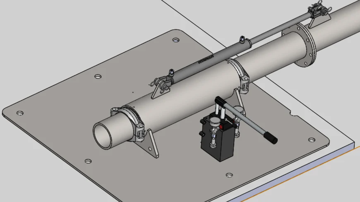
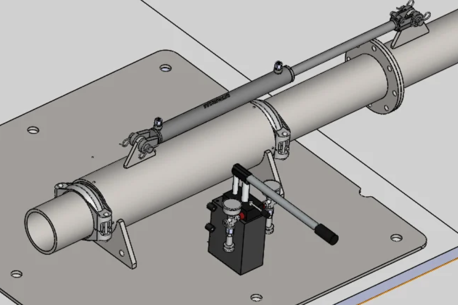
- Designed and implemented the complete hydraulic lifting system
- Calculated required lifting forces and safety factors
- Selected appropriately rated cylinders, hoses, fittings, and valves
- Sourced and ordered all hydraulic components
- Assembled the hydraulic system and fabricated custom mounting brackets in-house
- Created fabrication-ready CAD models and supported machining planning
- Coordinated directly with manufacturers and oversaw welding and fabrication
- Participated in system deployment aboard a research vessel and trained crew on setup and operation
Key Engineering Challenges
- Maintaining structural integrity during deployment and retrieval in rough seas
- Preventing corrosion and material brittleness in cold marine environments
- Avoiding vortex-induced vibrations that could affect structural life or sonar accuracy
- Ensuring manufacturability and weld quality for a field-ready system
Solutions & Technical Highlights
- Simulated wave and impact loads using FEA to identify stress concentrations
- Modified structural geometry to reduce vortex shedding and dynamic loading
- Selected cold-resistant, corrosion-resistant marine alloys and coatings
- Worked directly with fabricators to ensure weld quality and dimensional accuracy
- Designed the system for safe handling, deployment, and recovery at sea
Results & Performance
- Successfully deployed from a large research vessel
- No structural failures during deployment or operation
- Stable sonar mounting enabled reliable data collection
- System operated effectively in cold marine conditions
What I Learned
This project reinforced the importance of designing for real operating environments, where hydrodynamic effects, material behavior, and fabrication quality all interact.
Issues like vortex shedding and weld integrity had the potential to cause long-term structural problems, highlighting the need for careful analysis and close coordination with manufacturers.
The project strengthened my experience in structural FEA, marine system design, fabrication oversight, and field deployment of engineered systems.
Want to know more about me? Check out more pages on my site
Mooring System for Antarctic Deployment
Mechanical Design | Analysis | Prototyping
AOcean Networks Canada required a long-duration mooring system to support multi-year scientific data collection in icy Antarctic waters. The system needed to remain operational under constant tension, ocean currents, ice movement, and biofouling, all while minimizing maintenance or intervention.
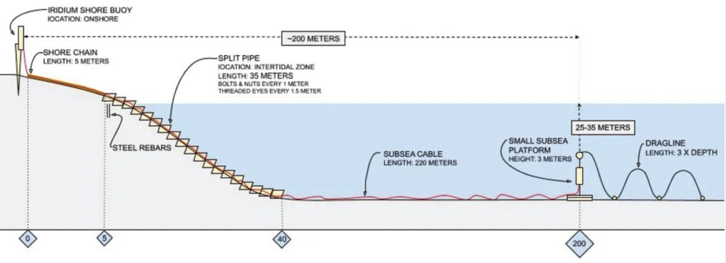
Objective
Design a reliable underwater mooring system capable of maintaining structural integrity and operational uptime over multiple years in sub-zero, high-load Antarctic conditions.
Tools & Technologies
- SolidWorks · FEA stress and fatigue analysis
- MATLAB / analytical calculations
- Marine-grade alloys and fasteners
- Materials testing · Cable and mooring hardware selection
My Role & Contributions
- Led the mechanical design of the mooring system, including anchors and tension-control components
- Performed structural and fatigue analysis for long-term cyclic loading
- Selected materials and coatings for corrosion resistance and cold-temperature performance
- Evaluated metal and synthetic cable configurations for fatigue life and chemical resistance
- Developed fabrication-ready CAD models and component specifications
Key Engineering Challenges
- Designing for multi-year service under continuous tension and cyclic ocean loading
- Preventing corrosion and material degradation in sub-zero saltwater conditions
- Mitigating the effects of ice movement and biofouling on system performance
- Ensuring reliability without maintenance in a remote Antarctic environment
Solutions & Technical Highlights
- Simulated drag and wave forces to determine required anchor capacity and line tension
- Conducted fatigue analysis for mooring lines and structural components
- Compared metal and synthetic cable options to balance strength, fatigue life, and corrosion resistance
- Selected marine-grade materials and coatings for long-term durability
- Designed the system to maintain consistent tension and stable positioning over extended deployments
Results & Performance
- Achieved approximately 98% operational uptime over a two-year deployment
- No structural failures during the deployment period
- Minimal performance loss due to biofouling
- Demonstrated reliable long-term anchoring in Antarctic conditions
What I Learned
This project reinforced the importance of designing for long-term reliability in harsh marine environments, where material selection, corrosion resistance, and cyclic loading all interact. Small oversights in cable fatigue, coating selection, or tension control could lead to premature failure, emphasizing the need for conservative design and realistic load modeling.
The project strengthened my experience in mooring system design, fatigue analysis, and material selection for multi-year deployments in extreme environments.
Want to know more about me? Check out more pages on my site
Protective Winch Cover
Marine Equipment Design | Fabrication | Durability Optimization
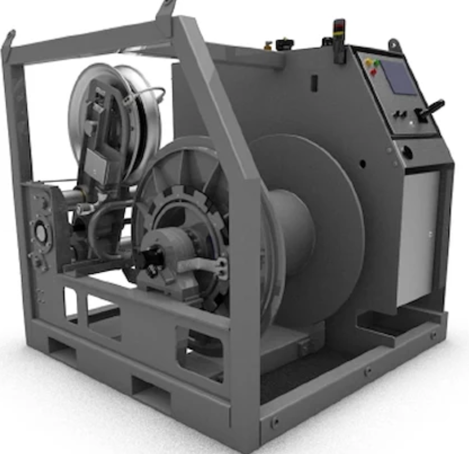
Winch systems on research vessels are regularly exposed to UV radiation, saltwater, and debris, which accelerates corrosion and increases maintenance frequency. A simple, durable protective solution was needed to extend equipment life without adding complexity to vessel operations.
Objective
Design and fabricate a protective cover that shields a marine winch from environmental exposure while remaining lightweight, durable, and easy to install or remove without tools.
Tools & Technologies
- SolidWorks
- CNC router
- Marine-grade materials and coatings
- Modular mechanical fastening design
My Role & Contributions
- Led the mechanical design of the protective winch cover and mounting interface
- Selected UV-resistant and marine-compatible materials for long-term durability
- Designed a modular, tool-free attachment system using snap-lock features
- Generated fabrication-ready CAD models
- Oversaw and performed CNC routing and assembly
Key Engineering Challenges
- Protecting the winch from UV, salt spray, and debris without trapping moisture
- Maintaining portability and quick access for maintenance
- Designing a durable structure that could withstand marine handling conditions
- Ensuring manufacturability with available shop tools
Solutions & Technical Highlights
- Designed a modular cover with snap-lock attachment features for tool-free installation
- Selected UV-stable materials and corrosion-resistant coatings
- Integrated coated frame supports to improve structural rigidity and longevity
- Optimized geometry for both protection and ease of removal during operations
Results & Performance
- Reduced field maintenance frequency by approximately 30%
- Extended winch surface lifespan by an estimated 2 years
- Provided durable environmental protection without increasing operational complexit
What I Learned
This project reinforced how relatively simple mechanical design improvements can significantly increase equipment reliability in harsh environments.
Material selection, drainage considerations, and ease of access all played a critical role in long-term performance.
The work strengthened my experience in marine equipment design, practical fabrication methods, and designing protective systems that balance durability with usability.
Want to know more about me? Check out more pages on my site
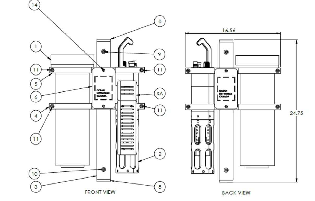
High-Pressure Instrument Housing
Pressure Vessel Design | Marine Systems | Precision Manufacturing
AML Oceanographic required a pressure-resistant housing to protect sensitive instruments operating at ocean depths equivalent to pressures up to 10,000 psi. The housing needed to maintain structural integrity, prevent leaks, and preserve sensor alignment under extreme conditions.
Objective
Design a compact, corrosion-resistant deep-sea instrument housing capable of withstanding pressures up to 10,000 psi while maintaining reliable sealing and dimensional stability.
Tools & Technologies
- SolidWorks · FEA structural analysis
- CNC machining · Precision tolerancing
- Marine-grade stainless steel
- High-pressure sealing systems
My Role & Contributions
- Led the mechanical design and FEA validation of the pressure housing
- Designed the body geometry and sealing interfaces for high-pressure operation
- Selected materials suitable for corrosion resistance and structural strength
- Oversaw material sourcing and precision CNC machining
- Verified tolerances and sealing performance during assembly and testing
Key Engineering Challenges
- Withstanding external pressures up to 10,000 psi without structural failure
- Preventing leakage under extreme pressure differentials
- Maintaining precise alignment for internal sensors
- Achieving tight tolerances while ensuring manufacturability
Solutions & Technical Highlights
- Performed FEA to validate structural integrity with a 1.5× safety factor
- Designed a double O-ring sealing system for redundant leak protection
- Used corrosion-resistant marine-grade stainless steel
- Specified fine machining tolerances to ensure sealing performance and alignment
Results & Performance
- Successfully deployed in deep-sea conditions
- No leaks observed during pressure testing or operation
- Maintained sensor calibration and alignment throughout deployment
- Met structural and sealing requirements for high-pressure environments
What I Learned
This project reinforced the importance of precision in pressure-vessel design, where small deviations in geometry or material selection can lead to sealing failures under extreme loads.
Achieving reliable performance required careful integration of structural analysis, sealing design, and machining tolerances.
The project strengthened my experience in high-pressure mechanical design, FEA validation, and coordinating precision manufacturing for deep-sea instrumentation.
Want to know more about me? Check out more pages on my site
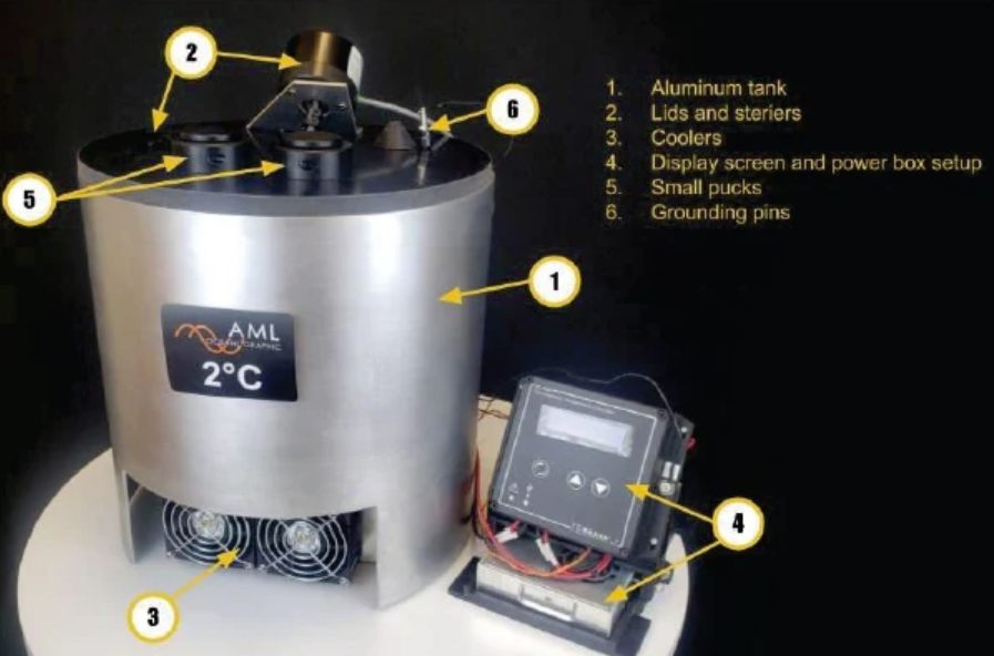
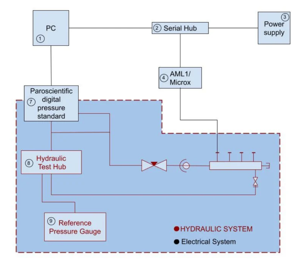
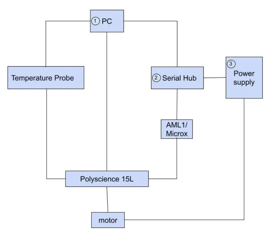
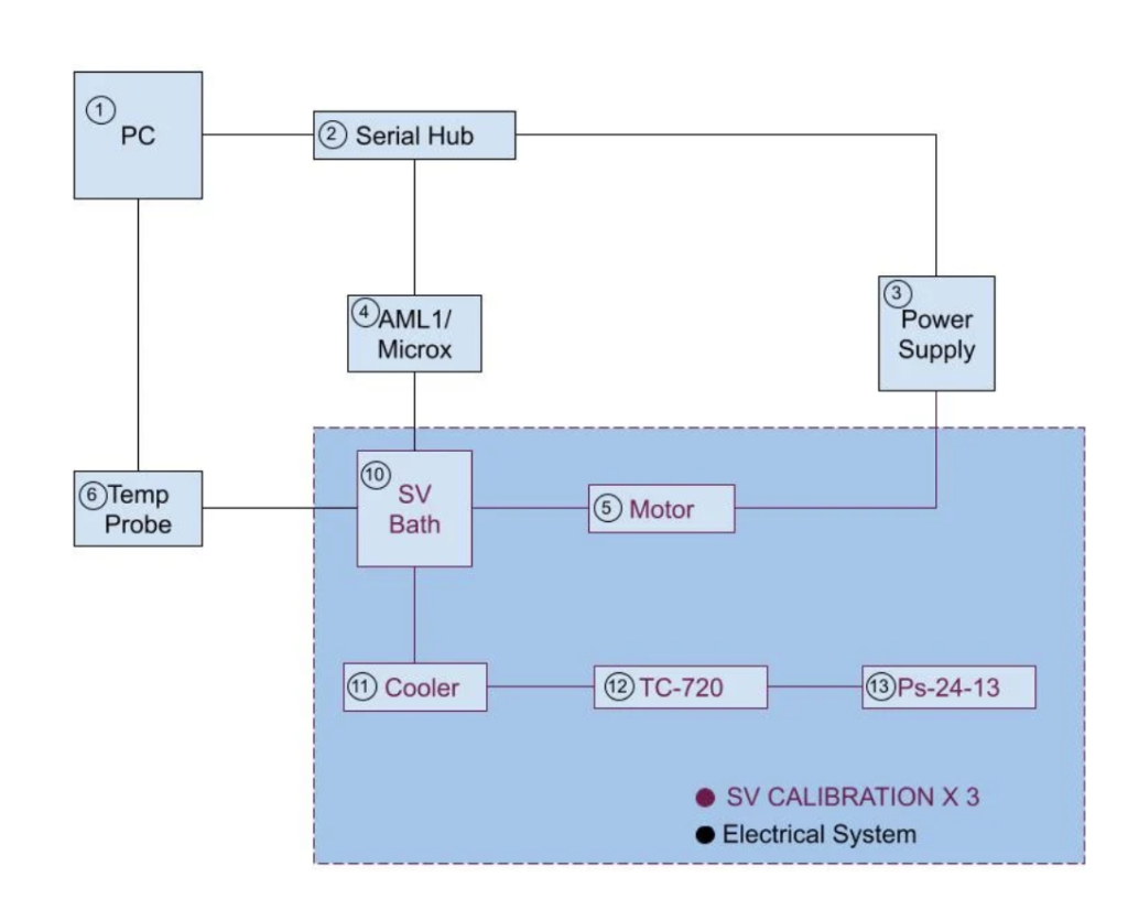
Calibration Test Branch for Oceanographic Sensors
Thermal Systems | Pressure Vessels | Instrumentation
Oceanographic sensors must be calibrated under realistic pressure and temperature conditions to ensure accurate measurements in deep-sea environments. A controlled, high-pressure test system was required to validate multiple sensors simultaneously while maintaining extremely tight thermal tolerances.
Objective
Design and build a high-pressure calibration system capable of maintaining temperature within ±0.05 °C while supporting multiple sensor channels under pressures up to 10,000 psi.
Tools & Technologies
- SolidWorks · Thermal control software
- Precision temperature sensors
- Pressure regulators and high-pressure fittings
- Layered insulation systems
My Role & Contributions
- Led the mechanical and thermal design of the calibration vessel and mounting interfaces
- Designed the temperature regulation system, including heater placement and insulation strategy
- Programmed the closed-loop temperature control system
- Integrated precision temperature sensors and pressure regulation hardware
- Supported assembly, testing, and calibration procedures
Key Engineering Challenges
- Maintaining uniform temperature distribution within the pressure vessel
- Achieving ±0.05 °C thermal stability under high-pressure conditions
- Ensuring reliable sealing and structural integrity at up to 10,000 psi
- Supporting multiple sensors without thermal or pressure interference
Solutions & Technical Highlights
- Implemented layered insulation to reduce heat loss and temperature gradients
- Used redundant temperature sensors for improved control accuracy
- Designed a feedback-controlled heating system for precise thermal regulation
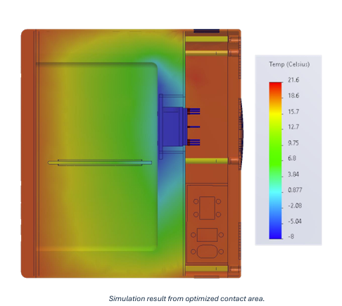
- Simulated heat flow within the vessel to optimize heater placement and insulation
Results & Performance
- Enabled simultaneous calibration of six sensors
- Maintained pressure up to 10,000 psi
- Achieved temperature stability within ±0.05 °C
- Provided a reliable, repeatable calibration environment for oceanographic instrumen
What I Learned
This project reinforced the importance of precise thermal management in instrumentation systems, where small temperature variations can significantly affect sensor accuracy.
Achieving tight temperature tolerances required careful integration of insulation, heater placement, and feedback control.
The project strengthened my experience in thermal system design, closed-loop control, and high-pressure instrumentation for scientific applications..
Want to know more about me? Check out more pages on my site
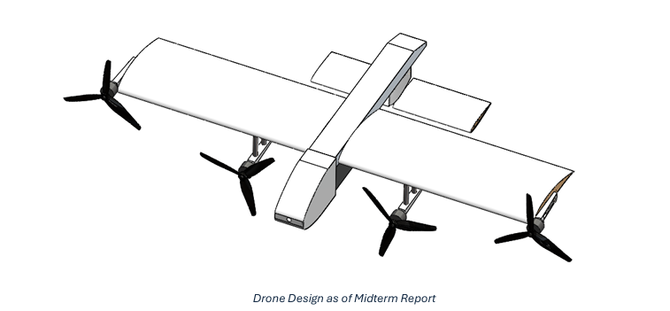
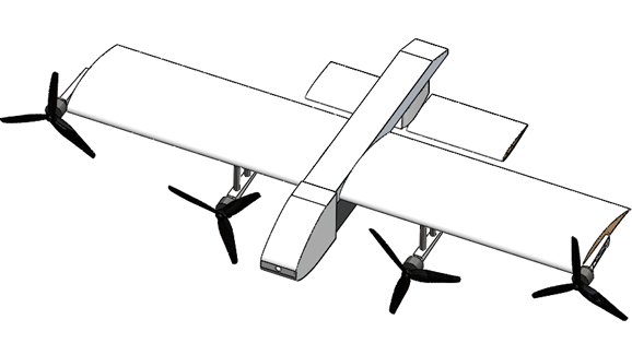
VTOL SAR Drone Development
UAV Design | Systems Integration | Propulsion & Power Analysis
Search and rescue operations in remote and mountainous regions of British Columbia require long-endurance aerial platforms capable of covering large areas efficiently. Traditional helicopters and commercial UAVs are often cost-prohibitive or limited in endurance, motivating the development of a lower-cost, fixed-wing VTOL solution optimized for extended flight times.
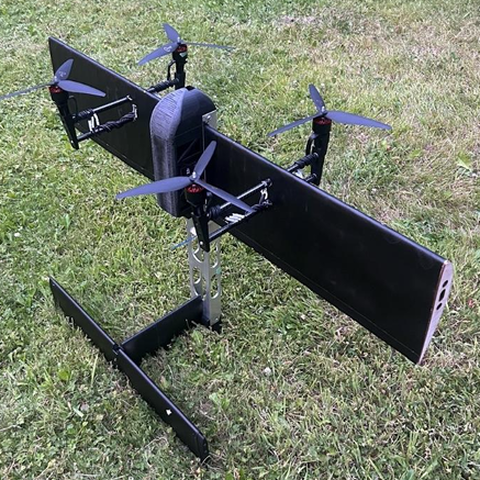
Objective
Design and develop a lightweight VTOL drone capable of vertical takeoff and landing with a target endurance of up to 90 minutes, suitable for wide-area scanning in SAR missions.
Tools & Technologies
- SolidWorks · ArduPilot · Pixhawk 6X
- MATLAB · FEA · CNC machining
- Power system modeling · UAV avionics integration
My Role & Contributions
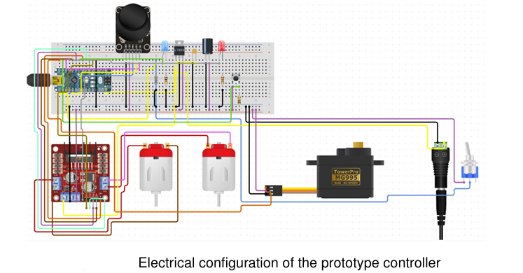
- Owned the complete electrical and avionics system, including all wiring, soldering, motor balancing, and electronic integration
- Designed and implemented the electrical layout and supported full avionics integration
- Conducted power budgeting, ground testing, and diagnostics of motor and avionics systems
- Developed and implemented all flight control and configuration code using ArduPilot
- Performed propulsion and endurance calculations to determine optimal motor, ESC, and battery sizing
- Led subsystem integration, including avionics, propulsion, and power distribution
- Sourced and validated all propulsion and power components
- Supported CAD design and structural layout of the airframe
Key Engineering Challenges
- Balancing endurance, cost, and structural weight within a compact airframe
- Maintaining flight stability across VTOL and cruise modes in variable wind conditions
- Integrating avionics and propulsion systems with minimal electrical losses
Solutions & Technical Highlights
- Selected a tail-sitter VTOL configuration to reduce mechanical complexity and aerodynamic drag
- Optimized battery capacity and ESC configuration to maximize cruise efficiency
- Used propulsion modeling and power analysis to inform component trade-offs
- Iteratively validated electrical and avionics systems through bench and subsystem testing
Results & Performance
- Produced a 4.7 kg prototype with a 1.2 m wingspan
- Achieved over 60% energy savings in cruise mode compared to hover-based flight
- Reduced projected system cost by approximately 70% relative to commercial SAR UAVs
- Demonstrated stable avionics and propulsion integration suitable for extended missions
What I Learned
This project reinforced the importance of tightly coupling avionics integration, electrical reliability, and propulsion modeling in UAV development. Small issues in ESC signaling, power distribution, or component matching had system-wide impacts on performance and reliability, highlighting the need for structured diagnostics and iterative testing.
The project strengthened my experience in UAV systems integration, electrical diagnostics, and early-stage flight platform development, particularly in identifying and resolving failure modes during prototype testing.
Want to know more about the project? Check out the full report
Want to know more about me? Check out more pages on my site
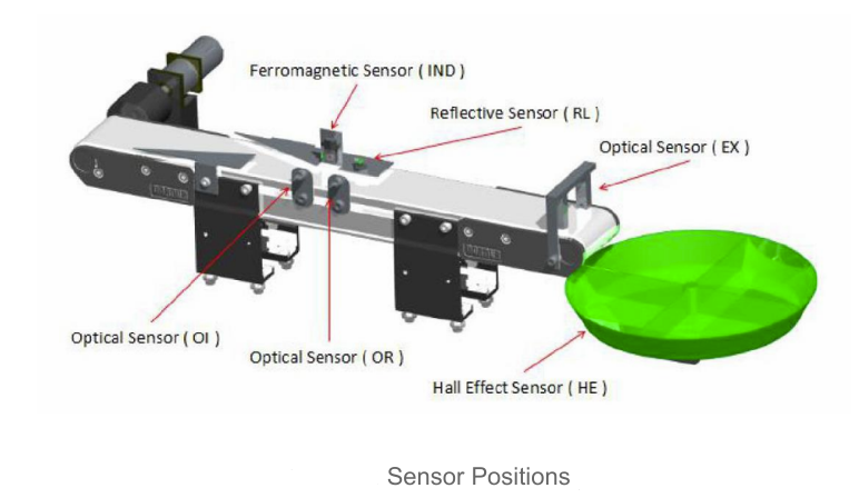
Automated Sorting System Using Microcontroller
Mechatronics | Embedded Systems | Real-Time Control
Manual material sorting in low-volume production and teaching labs is slow, inconsistent, and error-prone. This project aimed to demonstrate how a low-cost microcontroller-based system could autonomously classify and sort multiple materials with high accuracy and repeatability.
Objective
Design and implement a fully autonomous sorting system capable of identifying and sorting four different materials (aluminum, steel, white plastic, black plastic) within a strict time constraint, using real-time sensor feedback and precise motor control
Tools & Technologies
- Real-time state machines · Modular embedded architecture
- Arduino Mega 2560 · C · Interrupts & ISRs · ADC · PWM
- Reflectivity sensors (SFH 310 NPN, OPB819Z) · Hall-effect sensors
- Stepper & DC motors · FIFO linked lists · LCD interface
My Role & Contributions
- Co-led embedded software development and system integration
- Designed and implemented interrupt-driven object detection and classification logic
- Developed a trapezoidal acceleration/deceleration algorithm for stepper motor control to improve reliability and reduce mechanical stress
- Implemented FIFO queue logic to synchronize sensing and sorting across conveyor stages
- Performed sensor calibration, system optimization, and full-load testing
Key Engineering Challenges
- Distinguishing materials with overlapping reflectivity values under variable ambient lighting
- Preventing missed events and belt stalls caused by concurrent interrupts
- Achieving fast bucket rotation without stepper motor stalling or overshoot
Solutions & Technical Highlights
- Implemented signal averaging and analog filtering to stabilize reflectivity readings
- Tuned ADC threshold bands to reliably classify all four materials
- Designed modular arithmetic logic to determine shortest-path bucket rotation
- Created a delay-based trapezoidal motion profile enabling fast, smooth stepper movement without loss of steps
- Used interrupt flags and state control to safely manage simultaneous sensor events
Results & Performance
- Sorted 48 objects in 37 seconds
- 0 misclassifications in final validation run
- Fully autonomous operation with no user intervention during sorting
- Met all timing and accuracy requirements of the project specification
What I Learned
This project reinforced the importance of tight integration between software timing, sensor reliability, and mechanical behavior in real-time systems. Small changes in delay, filtering, or interrupt logic had system-wide effects, highlighting the need for iterative testing under realistic operating conditions.
The importance of tightly coupling software timing, sensor reliability, and mechanical behavior in real-time embedded systems. Small changes in interrupt handling, delay tuning, or sensor filtering had system-wide effects, reinforcing the need for structured testing under realistic operating conditions.
The project strengthened my experience in embedded C, real-time system design, and hardware–software integration.
Want to know more about the project? Check out the full report
Want to know more about me? Check out more pages on my site
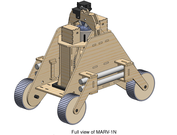
Mine Detection Robot
Mechanical Design | Robotics | Prototyping
Millions of unexploded landmines remain active worldwide, posing long-term safety risks in post-conflict regions. Traditional detection methods are slow, dangerous, and resource-intensive. This project explored a low-cost, mechanically driven robotic solution capable of safely triggering buried landmines without exposing humans to danger.
Objective
Design and prototype a lightweight, manually deployable robotic platform capable of triggering buried landmines through controlled mechanical impact, while maintaining mobility, repeatability, and structural integrity.
Tools & Technologies
- SolidWorks · Mechanical simulation · Spring analysis
- Arduino · 3D printing · Laser cutting
- Rapid prototyping · System integration · Impact testing
My Role & Contributions
- Designed, wired, and programmed the complete Arduino-based control system
- Implemented actuation logic, timing control, and system safeguards
- Integrated electronics with the mechanical impact mechanism and mobility platform
- Contributed to overall mechanical system design, including chassis layout and impactor integration
- Co-designed the spring-driven impactor mechanism
- Led the design and implementation of the recoil damping system to protect onboard electronics and structure
- Supported fabrication, assembly, and field testing
Key Engineering Challenges
- Delivering sufficient impact energy to reliably trigger simulated mines
- Preventing recoil forces from damaging the robot or destabilizing its motion
- Designing a system that could be safely reset and redeployed in the field
Solutions & Technical Highlights
- Performed spring force and energy calculations to size the impact mechanism for consistent triggering
- Implemented mechanical locking and release mechanisms to isolate impact forces from the chassis
- Designed a recoil damping system that absorbed excess energy and protected sensitive components
- Validated impact performance using simulated buried mines under controlled test conditions
Results & Performance
- Successfully triggered 100% of test mines during trials
- Achieved repeatable impact performance without structural damage
- Built a field-resettable robotic prototype with full mobility and mechanical triggering capability
What I Learned
This project reinforced the importance of tight integration between mechanical energy transfer, structural integrity, and system control in robotics applications.
Small changes in spring stiffness, damping, or locking geometry had system-wide effects on impact reliability and robot stability, highlighting the need for iterative testing under realistic operating conditions.
The project strengthened my experience in mechanical system design, energy management, and hardware integration, particularly in designing mechanisms that safely deliver high forces while protecting surrounding structures and components.
Want to know more about the project? Check out the full report
Want to know more about me? Check out more pages on my site
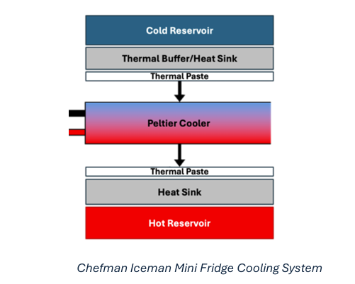
Thermal Optimization of Mini Fridge
Thermal Systems | CFD | Design Optimization
Thermoelectric mini fridges often suffer from low efficiency due to poor heat sink geometry and limited cold-side contact area. These thermal design limitations reduce cooling capacity and increase power consumption.
Objective
Reverse engineer a commercial mini fridge and improve its thermal performance by optimizing the cold block and heat sink geometry using CFD and thermal simulation, while maintaining low manufacturing cost.
Tools & Technologies
- SolidWorks Simulation · Simcenter Star-CCM+ · MATLAB
- Parametric CAD modeling · Conjugate heat transfer
- Thermal resistance and COP analysis
My Role & Contributions
- Led the thermal analysis and design optimization of the cooling system
- Built and ran CFD simulations of the hot-side heat sink using Simcenter Star-CCM+
- Performed steady-state thermal simulations of the cold side using SolidWorks
- Conducted parametric studies on fin geometry, spacing, and cold block contact area
- Used MATLAB to model fin performance and guide design decisions
- Compared performance gains against manufacturing cost increases to select practical solutions
Key Engineering Challenges
- Low baseline coefficient of performance (COP) from the thermoelectric system
- Inefficient heat dissipation on the hot side
- Limited thermal contact area on the cold side
- Need to improve performance without large increases in manufacturing cost
Solutions & Technical Highlights
- Reverse engineered the cooling system and isolated key thermal bottlenecks
- Increased cold block contact area to improve temperature distribution
- Ran CFD studies on multiple heat sink geometries, including split fins, triangular fins, and gyroid structures
- Performed parametric analysis of fin height, spacing, and count to identify efficient configurations
- Selected a triangular fin heat sink with increased fin count as the optimal performance-to-cost solution
Results & Performance
- Improved coefficient of performance (COP) by up to 53%
- Reduced internal cold block temperature by 4.3 °C
- Achieved performance gains with only a 9.9% increase in manufacturing cost
- Identified design changes that significantly improved heat transfer efficiency
What I Learned
This project reinforced the importance of tightly coupling thermal modeling, geometry, and cost constraints when designing energy-efficient systems.
Small changes in fin geometry, spacing, or contact area produced significant system-level effects on temperature distribution and COP, emphasizing the need for structured parametric studies and validation.
The project strengthened my experience in CFD-driven design, thermal system optimization, and using simulation results to guide practical, cost-constrained engineering decisions.
Want to know more about the project? Check out the full report
Want to know more about me? Check out more pages on my site
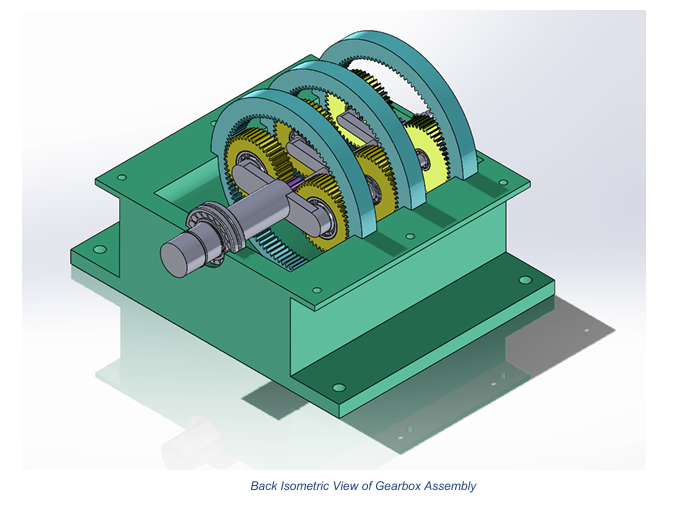
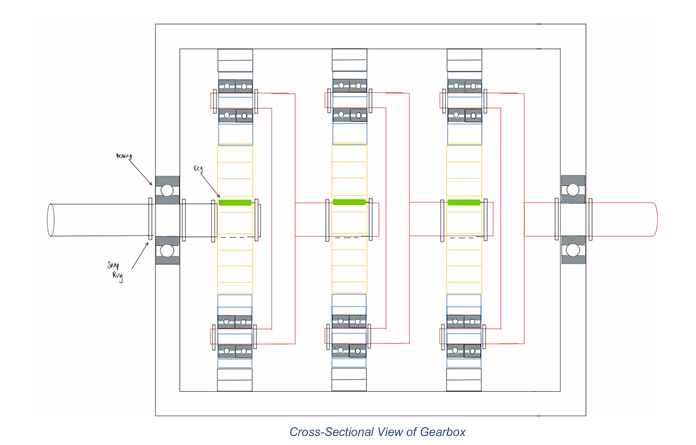
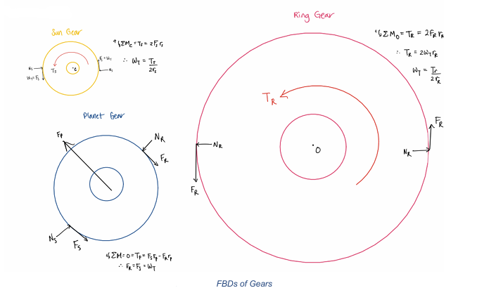
Planetary Gearbox for Ferris Wheel
Mechanical Design | Analysis | Prototyping
Amusement ride systems require highly reliable mechanical components, especially in child-focused applications where safety, durability, and low maintenance are critical.
Objective
Design a three-stage planetary gearbox for a small Ferris wheel capable of operating safely under cyclic loading conditions for a minimum of 20 years. The design focused on achieving high efficiency, adequate torque reduction, and long service life while meeting strict safety constraints.
Tools & Technologies
- SolidWorks (CAD modeling and assembly)
- AGMA gear design standards
- Fatigue and failure analysis methods
- MATLAB / analytical calculations
My Role & Contributions
- Led gearbox concept selection and mechanical design
- Performed gear sizing, torque calculations, and ratio optimization
- Conducted bending, surface, and fatigue failure analyses for all gear stages
- Designed shafts and performed fatigue analysis at critical stress points
- Selected and sized bearings to meet a 20-year L10 life requirement
- Created full CAD assembly and component drawings
Key Engineering Challenges
- Achieving the required high gear ratio while maintaining efficiency
- Ensuring long service life under cyclic loading conditions
- Minimizing size and maintenance requirements while maintaining safety factors
Solutions & Technical Highlights
- Selected a three-stage planetary gearbox to achieve the required reduction
- Performed bending, fatigue, and surface stress analysis for each gear stage
- Designed shafts with safety factors above 3.0 at critical points
- Sized bearings to meet the required 20-year operational life
- Optimized the assembly to reduce the need for additional support structures
Results & Performance
- Completed full gearbox and shaft assembly design
- Achieved safety factors greater than 3.0 across gears and shafts
- Designed bearing system validated for 20-year service life
- Produced full CAD models and assembly documentation
What I Learned
This project strengthened my understanding of fatigue-driven design in rotating mechanical systems.
It highlighted the importance of designing for long-term reliability, not just peak loads, and showed how early safety-factor planning directly impacts durability and maintenance requirements.
The work also deepened my experience with gear design, shaft analysis, and bearing life calculations using industry standards.
Want to know more about the project? Check out the full report
Want to know more about me? Check out more pages on my site